Taming Boundaries
Balancer accurately preserves and optimizes all types of boundaries defined by the model attributes. However, absent or excessive boundaries may dramatically deteriorate the visual appearance and optimization quality of the resulting 3D models. Thus, before optimizing your model, it is important to inspect its boundaries and repair it if necessary.
Balancer recognizes the following five types of boundaries:
 Surface boundaries
 Texture coordinates (UV) boundaries
 Normal boundaries
 Smoothing groups boundaries
 Material or layer boundaries
Inspecting Boundaries
To view your model boundaries
- press
 toolbar button or
 - use the menu and select View | Boundaries | All Boundaries.
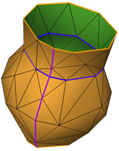
The following example demonstrates how Balancer visualizes boundaries.
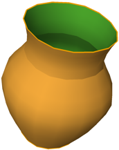 |
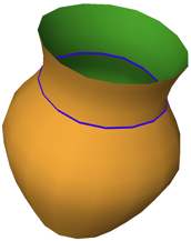 |
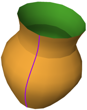 |
Optimizing Boundaries
Balancer accurately preserves and optimizes all the boundaries for all the meshes in the LOD hierarchy.
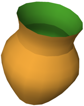
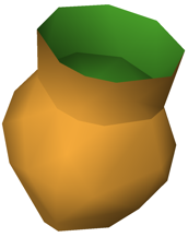
The lower row of the following example is a simplified model with 81 triangles (21%) of the 384 original triangles.
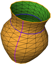 |
 |
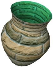 |
| Original with 384 triangles. All boundaries and edges are on. | Original. Only shading. | Original. Textured. |
 |
 |
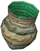 |
| Simplified model with 81 triangles. | Simplified model with 81 triangles. Only shading. | Simplified model with 81 triangles. Textured. |
Joining normals
Some applications export 3D models without optimizing the model attributes. The values of the model normals may be duplicated, or otherwise inaccurately defined. Balancer allows to solve this problem by joining the normals of adjacent triangles if the angle between them is less than a specified threshold degree. Join your model normals if viewing the normal boundaries reveals unnecessary or irrational normal boundaries.
To join normals
- use the menu and select Tools | Join Normals.
To modify the threshold value
- use the menu and modify the required threshold in Tools | Preferences | Joining.
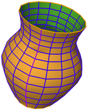
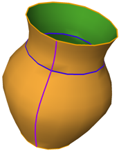
The following example demonstrates how Balancer joins normals for various threshold values.
 |
 |
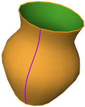 |
| Original | After joining normals (threshold 0 degrees) | After joining normals (threshold 25 degrees) |
Joining texture coordinates
Similarly to the normals, the model UVs can be inaccurately defined. Balancer allows to join UVs that are closer than a specified threshold value. Join your model UVs if viewing the UVs boundaries reveals unnecessary or irrational UV boundaries.
To join UVs
- use the menu and select Tools | Join Texture Coordinates.
To modify the threshold value
- use the menu and modify the required threshold in Tools | Preferences | Joining.
Joining vertices
Depending on the authoring application the vertices of 3D models can be duplicated, or even cannot necessary coincide when they should share their positions between different layers or material submeshes. To accurately preserve and at the same time optimize boundaries between mesh layers or material submeshes, vertices with the same positions must be joined.
Balancer allows to join vertices that are closer than a specified threshold value. Join your model vertices if the model has surface boundaries between its layers or material submeshes.
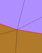
Joining vertices typically turns surfaces boundaries into normal, UV or material boundaries, which is normal. However, the resulting unnecessary normal or UV boundaries can be eliminated by joining normals or UVs respectively.
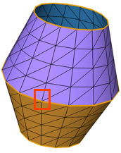
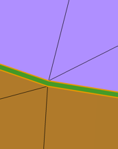
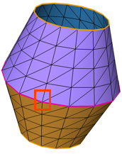
The following example demonstrates that joining vertices can dramatically affect the model optimization.
 |
 |
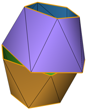 |
| Original with 256 triangles. Note the surface boundary between the two materials. | Zoom in reveals a tiny gap between the materials. | Simplified model with 26 triangles. Surface boundaries no longer visually coincide. |
 |
 |
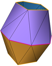 |
| Original after joining vertices. The surface boundary turns into material boundary. | Zoom in shows that the gap is closed. | Simplified model with 26 triangles. Material boundaries are preserved and optimized. |

